
EFB SERIES · PART 2 OF 8 — Technology, Security & Safety · Series Hub · ← Part 1 · Part 3 →
TL;DR — What are EFB hardware classes? Class 1 EFBs are portable devices with no aircraft interface; Class 2 are portable but connect to aircraft power and data through an approved interface; Class 3 are fully installed, certified systems. Current FAA guidance (AC 120-76E) has replaced the class labels with a simpler distinction — portable versus installed — but the old vocabulary still dominates fleet discussions, STCs, and EASA material.
The class system died years ago, and yet you cannot spend a day in flight ops without hearing “Class 2.” That tension — a deprecated regulatory vocabulary that remains the industry’s working language — is where any serious discussion of EFB hardware has to start. The class model still describes something real: how attached the box is to the airplane determines how much certification it drags with it.
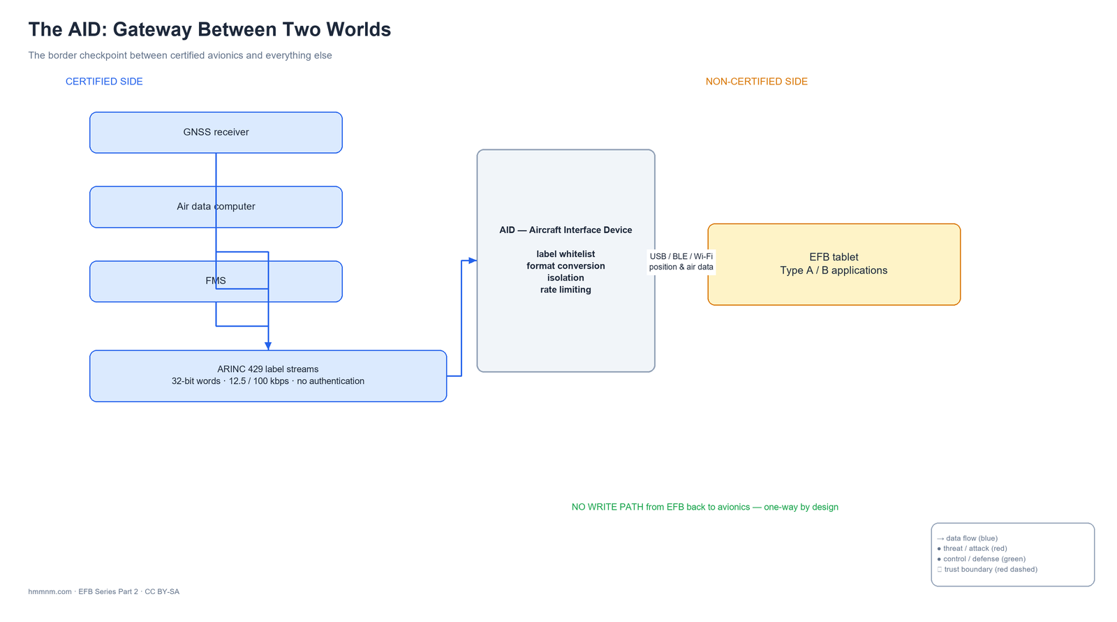
This post covers the classification system and its successor, the physical components that make up a real EFB installation (displays, mounts, power, environmental qualification), and the single most important piece of hardware in the ecosystem: the Aircraft Interface Device — the gateway between certified avionics and everything else. Keep that AID diagram in mind; Parts 6 and 7 of this series practically live inside it.
How Regulators Classify EFB Hardware
Hardware classification answers one question: how integrated with the certified aircraft is the device? The greater the integration, the greater the certification burden — because the more the device’s failure becomes the aircraft’s failure.
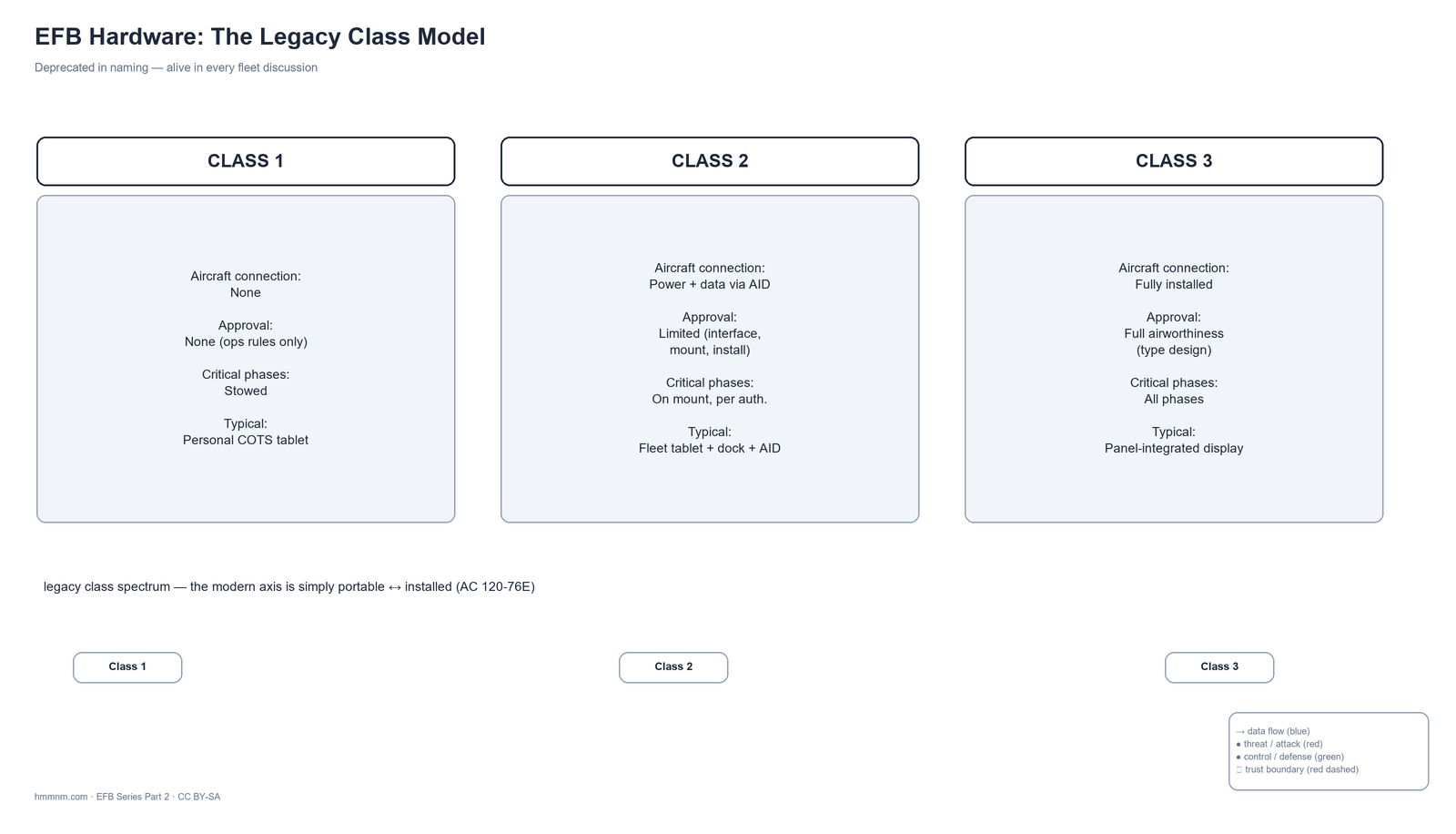
Table T2.1 — The legacy class model at a glance
| Attribute | Class 1 | Class 2 | Class 3 |
|---|---|---|---|
| Connection to aircraft | None | Power + data through approved interface (AID) | Fully integrated |
| Airworthiness approval | None (operational rules only) | Limited — interface, mount, installation | Full — part of aircraft type design |
| Critical phases (T/O, landing) | Stowed | Usable on approved mount per authorization | Usable (installed display) |
| Typical example | Personal COTS tablet, untethered | Fleet tablet + dock/mount + AID feed | Panel-integrated EFB display |
| Failure containment | “It’s a suitcase item” | Procedures + mount/interface approvals | Certified design assurance |
Class 1 — the untethered portable
A Class 1 EFB is a commercial off-the-shelf device — historically a laptop, today a tablet — that is not connected to the aircraft in any way: no aircraft power, no data interface. It runs on its own battery and is treated much like other portable electronic devices (the PED rules of 14 CFR 91.21 / 121.306 territory). During taxi, takeoff and landing it is stowed. No airworthiness approval attaches to the device itself; any oversight is purely operational.
Class 2 — portable, but plugged into the airplane
Class 2 is where most of the world’s EFB fleet lives. The device remains portable — it can be carried to and from the aircraft — but it connects to the aircraft: typically ship’s 28 V DC power and, crucially, a data feed through an Aircraft Interface Device. It usually lives on an approved mount. This combination (portable device + installed interface + installed mount) is what triggers “limited” airworthiness approval: the interface and mount affect the aircraft, so they need installation approval — an STC-class exercise — even though the tablet itself remains outside the type design.
Class 3 — installed equipment
A Class 3 EFB is part of the aircraft. Panel- or pedestal-mounted displays, integrated power, full environmental qualification (RTCA DO-160G), and software that may need full design assurance (DO-178C, Part 3’s Type C). Class 3 hardware appears on newer type designs and retrofits; it is capable, expensive, and increasingly shares hardware lineage with installed avionics rather than with consumer tablets.
The shift: portable vs installed
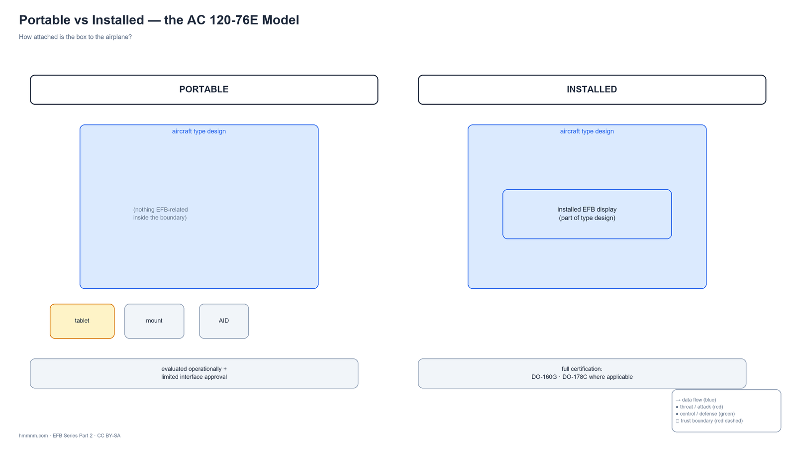
FAA guidance — from AC 120-76D (2017) onward, carried into the current AC 120-76E — deprecated the class numbers in favor of a spectrum: portable versus installed — recognizing that the real regulatory question is not a class label but the nature of each connection point (power? data? mount? display integration?). EASA material and a decade of fleet documentation still use classes, which is why any engineer or auditor must be bilingual.
The Physical Components of an EFB System
A real EFB installation is five components working together: display, mount, power, data interface, and environment. Get any one of them wrong and the system fails its approval or, worse, its crew.
Displays: consumer, ruggedized, installed
Table T2.3 — Three display classes
| Attribute | Consumer tablet | Ruggedized tablet | Installed display |
|---|---|---|---|
| Brightness / readability | Good indoors, marginal in direct sun | High-brightness, anti-glare treatments | Designed for cockpit lighting |
| Temperature range | ~0–35 °C operating | Extended (roughly −20 to +55 °C classes) | DO-160 qualified |
| Ingress / durability | Consumer-grade | Sealed, drop-rated | Panel-integrated |
| Certification burden | None on hardware | None on hardware itself | Full |
Sunlight readability is the perennial consumer-tablet weakness: cockpit daylight can exceed what a consumer panel renders legibly, which is why viewability tests are part of EFB evaluations. Night operations invert the problem — a display bright enough for noon is a dark-cockpit hazard at 3 a.m. unless brightness discipline is enforced (Part 8’s human-factors section returns to this).
Mounting and stowage
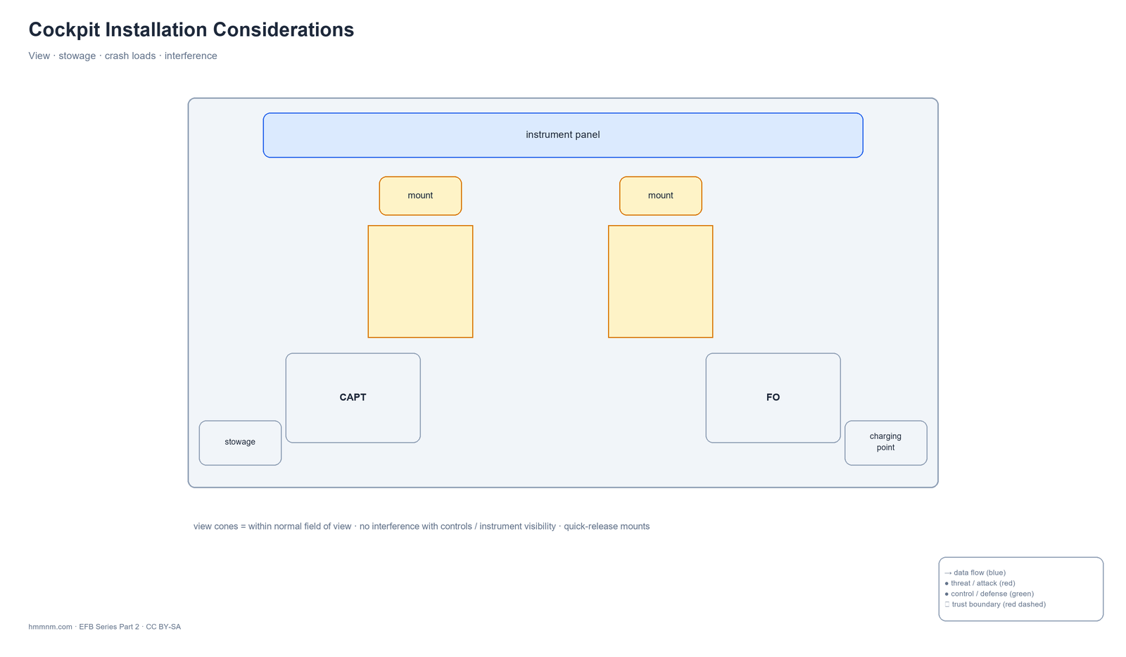
A mount is not a convenience; it is a certification item. Requirements concentrate on: viewability (the screen must sit within the pilot’s normal field of view without significant head movement), non-interference (nothing may obscure controls, switches, or instrument indications), quick-release (rapid detaching for egress or stowage), and crashworthiness — the mount must hold under forward inertia loads, with the commonly cited criterion around 9 g (check the applicable STC criteria for your installation). Stowage matters equally: a loose 700-gram tablet becomes a projectile under turbulence or a rejected takeoff.
Power and battery endurance
The power chain typically runs aircraft 28 V DC through a converter to the tablet (today usually via USB-C power delivery). The battery policy is where operations and safety meet: operators commonly require the device to hold — fully charged at departure — at least 130–150% of the planned flight time, with staged low-battery warnings. That margin is a policy norm, not a universal regulation; the governing text is the operator’s approved EFB program (Part 5). Battery discipline also includes the unglamorous rules that matter in Part 8: attended charging, no charging during critical phases where policy forbids it, and spare-battery carriage limits.
Environment and EMI: why consumer gear isn’t automatically legal
Aircraft are electromagnetically hostile, and their systems are unforgiving of interference. Installed and interfaced equipment is qualified against RTCA DO-160G — environmental conditions for airborne equipment — including Section 20 (radio-frequency emission) and Section 21 (RF susceptibility), plus lightning and HIRF considerations for external/installed kit. A consumer tablet that emits within limits for a living room has never been tested to DO-160 criteria; that gap is precisely why hard-mounting consumer hardware in a cockpit requires an installation approval with an interference assessment, and why “the iPad caused a NAV flag” anecdotes are taken seriously rather than laughed off.
The Aircraft Interface Device — Gateway Between Two Worlds
The AID is a data gateway that copies filtered information from the certified avionics side to the non-certified EFB side, while blocking influence in the other direction. It is the single most consequential hardware component in this entire series.
What the AID actually does
On the certified side of the boundary, the aircraft’s sensors and computers — GNSS receivers, air data computers, the FMS — publish their parameters as streams of words on ARINC 429 buses. On the non-certified side, a tablet wants a small subset of that: position, track, altitude, airspeed, heading — enough to drive a moving map. The AID sits between:
- Terminates avionics buses (ARINC 429; ARINC 717 data on some installations; A664/AFDX networks on IMA-generation aircraft),
- Filters and whitelists the labels it re-publishes — the EFB gets only what it needs,
- Converts formats and transport — re-publishing the filtered set over USB, Bluetooth or Wi-Fi to the tablet,
- Enforces isolation — in a compliant installation there is no write path from the EFB back into avionics. Information flows one way: airplane to tablet.
ARINC 429 in sixty seconds
Because Part 6 will attack this bus, it deserves a proper introduction here. ARINC 429 (the AEEC’s Mark 33 Digital Information Transfer Standard) is the workhorse avionics bus since the 1970s-80s: unidirectional, single-transmitter-to-multiple-receivers (commonly cited around 20 sinks per bus), running at 12.5 or 100 kbps, carrying 32-bit words whose first 8 bits — the label — identify the parameter (e.g., a specific label for computed airspeed on that installation’s bus architecture).
Table T2.2 — ARINC 429 quick facts
| Property | Value |
|---|---|
| Topology | Unidirectional, one source → multiple sinks |
| Speed | 12.5 kbps (low) / 100 kbps (high) |
| Word | 32 bits: label (8) · SDI (2) · data (19) · SSM (2) · parity (1) |
| Typical EFB-relevant content | Position, altitude, airspeed, heading, track |
| Security property | None designed in — no authentication, no encryption (designed 1970s, pre-threat-model) |
That last row is not a criticism of 1970s engineers; it is the design fact that Part 6’s most dramatic case study turns on.
The commercial landscape
AIDs are made by a small set of avionics suppliers — Teledyne Controls’ DAC family, Astronautics, Collins Aerospace and others populate the market. The exact box matters less than the pattern: every connected-EFB fleet has one, it is the choke point between two regulatory worlds, and it is therefore both the most defensible and the most targeted component in the ecosystem — the theme Parts 6 and 7 develop.
Class Selection Trade-offs
There is no best class; there is a best match to fleet economics and approval appetite.
- Class 1-style portables (untethered): minimal approval friction, minimal capability — no own-ship position feed, stowage requirements, battery anxiety. Common in general aviation and as backup devices in bigger operations.
- Class 2-style portable+interface: the industry default — consumer-hardware economics (cheap, replaceable, annually refreshed) with just enough integration (AID feed, mount) to unlock moving maps and ship’s power. The cost is managing the certified/non-certified boundary forever.
- Class 3 installed: maximum capability and integration, minimum flexibility — you certify once and live with it; display refresh cycles follow aircraft economics, not consumer ones.
The trade ultimately reduces to the boundary: the closer the EFB sits to the airplane, the more the airplane’s certification regime claims it. Everything the next part covers — software classes — exists to manage that same boundary from the other side.
Tomorrow, Part 3: the software that runs on all this hardware — Type A, Type B, Type C, and why one question (“what happens when it’s wrong?”) decides everything.
Key Takeaways
- Class 1/2/3 describe integration with the aircraft; AC 120-76E reframed it as portable vs installed — but the old vocabulary persists everywhere.
- Interfaced portable (Class 2-style) installations are the global default: consumer-tablet economics plus a limited installation approval for mount, power and interface.
- Mounts, viewability, stowage and crash loads are certification items, not accessories.
- DO-160G (EMI sections 20/21 among others) is why consumer hardware can’t simply be hard-mounted without approval.
- The AID is the gateway between certified avionics and the non-certified EFB — filter, whitelist, format-convert, isolate.
- ARINC 429: 32-bit words, 12.5/100 kbps, unidirectional — and designed with zero authentication.
- Battery endurance norms (≈130–150% of sector time) are operator policy, not universal law — Part 5 covers where policy comes from.
FAQ
What is a Class 2 EFB?
A portable EFB — usually a tablet — connected to the aircraft through an approved interface (typically an AID providing filtered data) and ship’s power, mounted on an approved mount. It needs limited installation approval for the interface and mount, but the device itself stays outside the aircraft’s type design.
Is a Class 3 EFB certified avionics?
Yes. A Class 3 EFB is installed equipment that is part of the aircraft type design, qualified under environmental standards like DO-160G, with software that may require full design assurance (DO-178C / Type C). It follows aircraft certification cycles, not consumer refresh cycles.
What is an Aircraft Interface Device (AID)?
A gateway box that reads certified avionics buses (ARINC 429/717, or A664), filters and whitelists the parameters the EFB needs, and re-publishes them over USB/Bluetooth/Wi-Fi to the tablet — enforcing one-way isolation so the EFB cannot write back to aircraft systems.
Can pilots use personal iPads as EFBs?
Only inside an operator’s approved EFB program that defines applications, configuration control, battery policy, mounting/stowage and training. Many operators instead issue fleet-managed devices precisely to keep configuration under control (Part 7’s MDM layer exists for this).
Why did the FAA stop using EFB classes?
The FAA replaced the class labels with a portable-versus-installed spectrum (AC 120-76D, retained in AC 120-76E) because the regulatory substance lies in each connection point — power, data, mount, display — rather than in a class number. Legacy documents, EASA material, and fleet vocabulary still use classes.
What is ARINC 429?
The dominant avionics data bus since the 1970s-80s: unidirectional, one transmitter to multiple receivers, 12.5 or 100 kbps, carrying 32-bit label-encoded words. It has no authentication or encryption — a design fact with security consequences covered in Part 6.
How long must EFB batteries last?
Common operator policy requires at least 130–150% of planned flight time at departure, with staged low-battery alerts. The exact figure lives in each operator’s approved EFB program rather than in a universal rule.
References
- FAA, Advisory Circular 120-76E — Electronic Flight Bag (faa.gov)
- FAA, Advisory Circular 91-78A — Use of Electronic Flight Bags (February 2024)
- SKYbrary, “Electronic Flight Bag (EFB)” — class/approval summary (skybrary.aero)
- RTCA, DO-160G — Environmental Conditions and Test Procedures for Airborne Equipment
- AEEC, ARINC 429 — Mark 33 Digital Information Transfer Standard
- EASA, AMC 20-25A — portable/installable EFB framework (ED Decision 2019/008/R)
- Teledyne Controls / Astronautics / Collins Aerospace — commercial AID documentation
[← Part 1: What Is an EFB?] · [Series Hub] · Part 3: EFB Software — Type A, B, C →
The complete 8-part series is published — bookmark the series hub for the full set.
Current as of September 2026 · standards verified against the latest revisions.
Educational reference only — always follow your operator’s approved EFB program and your NAA’s current guidance.
Author: hmmnm.com editorial team · hmmnm.com